


MindCAD 2D Modelling 2018 release offers the following new features and enhancements:
Enhanced project creation
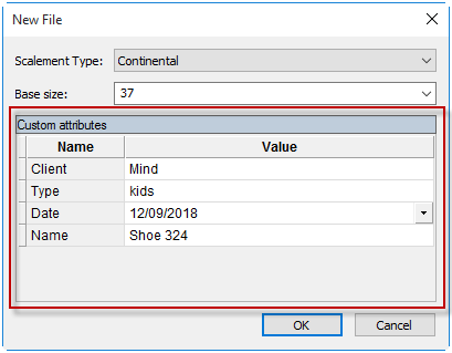
When creating a new file, filling the model PDM Custom attributes is now available. Those attributes are also available for editing in Project Properties.
Enhanced import processes for DXF, JPG and HPGL
It is possible to import several files simultaneously. (dxf, jpg).
HPGL importer improvement to cope with badly formatted instructions.
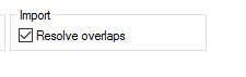
New Resolve overlaps option to ensure there are no overlapped geometry/images when importing multiple files in a single operation. When this option is disabled, all imported geometry/images will align to the canvas origin.
Directly import geometry/images to parts with automatic alignment.
Enhanced Measurement units
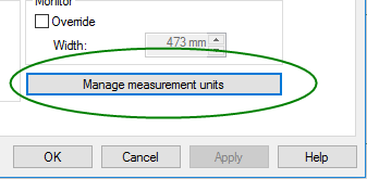
New specialized measurement unit management interface, allowing configuration of input and output unit formats for each measure type.
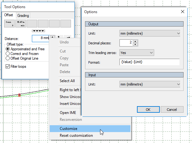
It is possible to access a measurement unit configuration window through the contextual menu of any unit text box. This interface allows the configuration of the input and output unit format.
Enhanced Layers control
New layer for measurements, now it is possible to show/hide the measurements layer.
Enhancements to Measurement tools
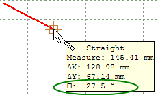
New angle restriction inside measurement tool through SHIFT modifier
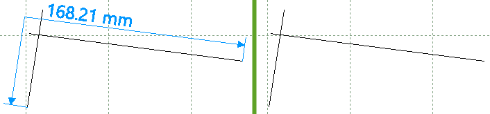
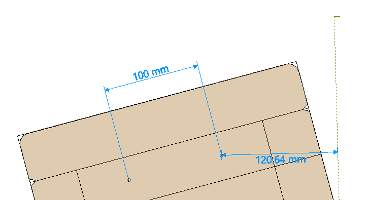
Added support for marks, punches and axis for straight active measurements
Canvas improvement
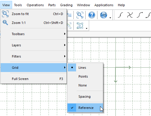
Possibility to add a referential to the grid, showing the origin of the document. This will allow designing with an explicit absolute referential, providing precise placement control.
Enhanced Adjust shell tool
With the Adjust shell tool, it is now possible to move the axis from the original shell to the new one.
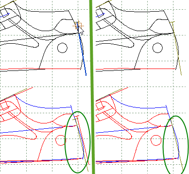
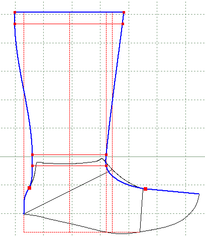
New Create Boot Lines tool
It is now possible to create boot lines based on shell lines. Restricted boot line editing to shell lines is available to ensure precise and consistent design
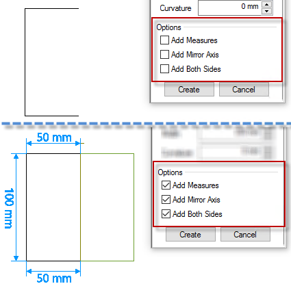
New Create Panel tool
New specialized tool to create rectangular like parts. It allows to automatically add corners, axis, and active measures.
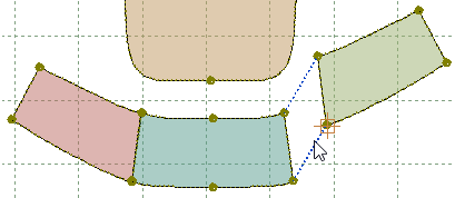
New Stitch Simulation tool
New tool to simulate the process of part stitching. This allows placing parts against each other by simply dragging, through matching point pairs or walking parts simulation. Smart features like locking parts in specific walking positions and adding reference lines is also available.
Lines editing
Several enhancements were added to the Line Offset tool.
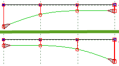
- It is now possible to hide the start and end section of a line offset.
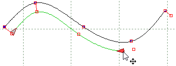
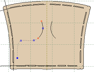
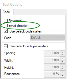
- New option to invert the offset direction. In a variable offset scenario, this applies the same complex offset distances configuration but in an opposite direction of the base line.
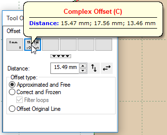
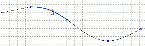
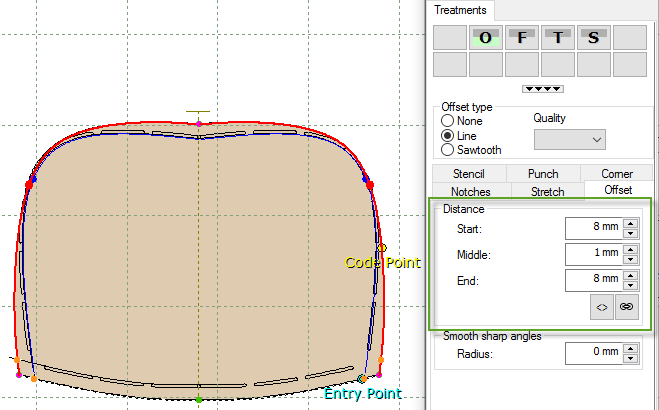
- New Complex offset template concept to be applied to a selected line. This makes it possible to apply a configuration of multiple offset distances to an arbitrary line. For operator convenience, a shortcut button with this configuration for quick assignment has been created.
On the Line Cut tool, it is now possible to cut a line in several places without exiting.
While adding points by XY values
-cursor is now tracking last inserted point to allow simpler, continuous and consistent interaction.
-combined XY input dialog
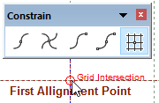
Snap functions are now available when marking digitizer table alignment points.
Usability Enhancements
In Parts List dialog, changes toward simplification and clarity were made.
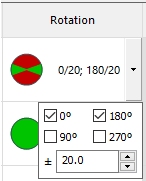
- revised and simpler interface to define base angle and range restrictions is now available
- units are now following global configuration under Preferences
- dimension measures (Width, Height) are now displayed based on part orientation.
On Parts Bar interface, additional functionality is now available.
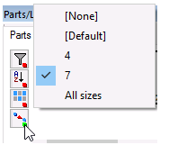
- filter by parts with variants
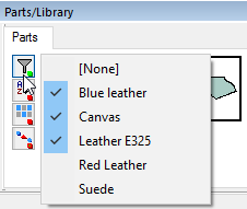
- filter parts by multiple groups
Parts modeling
Multiple selection of parts in Parts Bar for multiple editing.
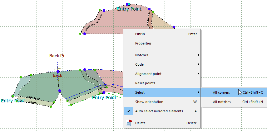
Ability to select and change all corners and notches of all selected parts.
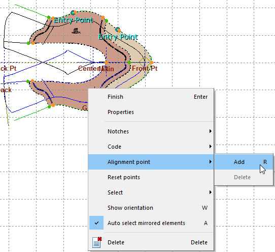
Assigning reference points for multiple parts in a single operation
Support for Treatments with variable offsets
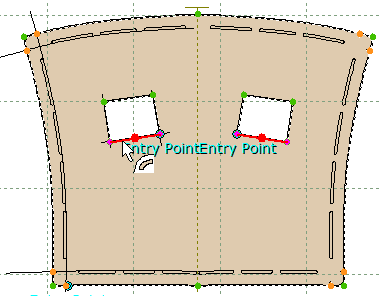
Auto mirror behavior now supports corners, notches, and holes
Mirrored Markers merge for machine optimization purposes

Only the visible line zone is applied to the part
Option to reverse the symbolic code applied to part border.
New default labels available, according to part orientation:
• %Width_Aligned% - Part bounding box width based on part orientation axis.
• %Height_Aligned% - Part bounding box height based in part orientation axis.